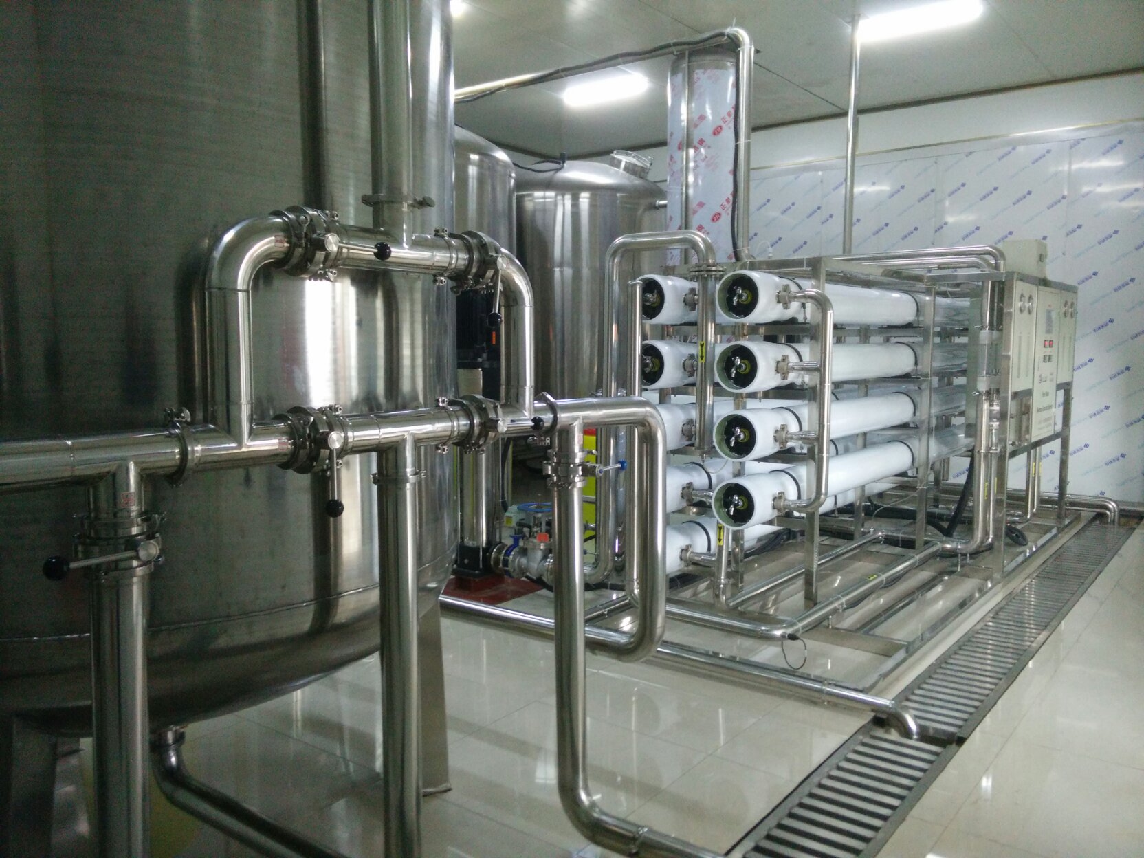
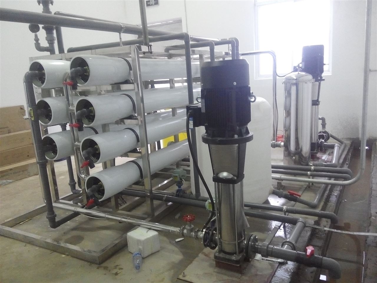
Reverse osmosis equipment installation instructions
Installation of reverse osmosis unit must be performed under the following conditions
Â
1.1 After the device is transported to the site, it should be placed indoors. The ambient temperature is not lower than 5 °C, and the Zui height should not be higher than 38 °C. When the temperature is higher than 35 °C, ventilation measures should be strengthened.
Â
Â
1.2 After the device arrives, it should be installed within one month, and the water test run should be carried out immediately. 2.1 The valve shall not be opened before the water test is carried out.
2.2. After the device is in place, the support points of the device should be adjusted so that the assembly is in a substantially horizontal position and the contact with the foundation is reliable.
2.2. The pipelines and valves connected to the water supply pump shall be degreased before connection, and the over-flow part of the water supply pump shall also be degreased.
2.2. The large output height of the water production pipe of the installation should be less than 8 meters.
2.2. If the cleaning device and the R/O device are connected by a hard pipe, the inlet and outlet pipes shall not be directly laid on the ground to avoid damage.
2.2 Installation of reverse osmosis membrane module
2.2.1 Check the inside of the pressure vessel for scratches or damage, and the leaked container must be replaced. Rinse the pressure vessel with clean water to remove all dirt and particles and clean up corrosion products or external impurities (including excess oil). Lubricate the inside of the casing from 1/2 of the slope to approximately 1/2" from the slope.
2.2.2 Check the surface of the membrane element for defects. If it is defective, it should be treated in time to avoid scratching the container. Take care to prevent the film from curling up the end of the device and if the defect is found to be unhandled, the manufacturer will handle it.
2.2.3 Lubricate the inside of the container with a mixture of approximately 50% glycerol-water. The mixture can be taken with a suitable size cotton cloth.
2.2.4 Insert the * membrane element into the inlet end of the pressure vessel. Leave the end of the element a few inches outside the container to connect the next membrane element.
2.2.5 Lubricate the O-ring of the connector with a small amount of lubricant and connect the connector to the upper and lower membrane elements. Install the next membrane element.
2.2.6 Connect all external piping.
2.3 Disassembly of pressure vessel and membrane components
The disassembly process is the reverse of the installation process steps. See the installation method for details.
Note: 1) Remove the components from the opposite direction of the water inlet of the component. When removing the components, they must be pulled out in parallel and must not be shaken left or right.
2) The loading components should be loaded from the direction of water inlet and pushed evenly with force. Do not force hard objects to be knocked in.
3) The disassembled components should be immediately immersed vertically in 0.5~1% sodium bisulfite solution, and should never be placed in the air.
Â
Â
3, RO reverse osmosis device debugging steps
3.1 The water inflow of the device is analyzed and tested. The results show that the water supply requirements can be adjusted before the water supply can be debugged.
3.2 Adjust the pressure control system of the high pressure pump.
3.3 Check whether the connection between all the pipes is perfect, whether the pressure gauge is complete, whether the low-pressure pipe connection is tight, and whether there is a shortage.
3.4 Fully open each pressure gauge switch and total inlet valve, concentrated water discharge valve, water discharge valve.
3.5 Start the pretreatment equipment and adjust the water supply to be larger than the total water intake of the unit.
3.6 There is no formaldehyde smell in the water to be discharged, and the total inlet valve of the device is closed.
3.7 Start the high pressure pump and slowly open the total inlet valve of the device. The total inlet pressure of the control unit is less than 0.5Mpa, flush for 5 minutes, and check whether the high and low pressure pipelines and instruments are normal.
3.8 Adjust the inlet valve and the concentrated water discharge valve to make the inlet pressure reach 1.0~1.4Mpa.
3.9 Detect the water conductivity of the product, open the product water outlet valve when the requirements are met, and close the production water discharge valve.
3.10 The debugging of the RO device is manual single-step operation. After the operation is normal, it can be switched to the automatic state, and the online instrument and PLC automatically control the operation.
Â
Â
4, the operation instructions of the reverse osmosis device
The operation of the reverse osmosis unit and the steps of the protective rinsing can be carried out automatically, and the time setting and flow rate of each step should be appropriately adjusted according to the following points.
4.1 Water production
The initial setting of the inlet pressure of the high pressure pump is 0.05Mpa, and the operation should be adjusted according to the site conditions.
4.2 Protective flushing
Pressing the concentrated water in the shutdown RO unit completely out of the set time, the preset time is 5 minutes.


Food Processing Nitrile Gloves
Food Processing Nitrile Gloves,Food Gloves Nitrile,Disposable Industry Gloves,Textured Finger Free Latex Gloves
Puyang Linshi Medical Supplies Co., Ltd. , https://www.linshimedicals.com